
The technique of robotic lobectomy II: left sided lobes
 0
0Abstract
Robotic lobectomy has been evolving over the past decade and has been shown to be an oncologically efficacious procedure. The Technique of Robotic Lobectomy I outlined the stepwise approach to robotic lobectomy of the right upper, right middle and right lower lobes. This paper outlines the stepwise technical approach to robotic lobectomy of the left upper and lower lobes. The accompanying paper, Technique of Robotic Lobectomy III: Control of Bleeding Complications, outlines a methodical technical approach for the control of catastrophic bleeding complications.
Keywords
Introduction
Cerfolio reported the technique of four-arm completely port-based lobectomy in 2011[1,2]. This technique has become the standard approach in robotic lobectomy. In the preceding manuscript: Technique of Robotic Lobectomy I, we outlined the stepwise approach to robotic lobectomy of the right upper, right middle and right lower lobes. This paper outlines the stepwise technical approach to robotic lobectomy of the left upper and lower lobes.
Left sided lobectomy
Left upper lobectomy
Instruments: 0° and/or 30° down viewing endoscope, 5 mm thoracic grasper, Cadiere forceps and curved bipolar dissector.
Figure 1 shows left sided port placement. The technique of port placement is similar to the right side. Begin by dividing the inferior pulmonary ligament and removing station #9 and #8 nodes [Figure 2]. The lung is retracted medially and anteriorly in order to remove lymph nodes from station #7. After the stomach has been decompressed, at this stage, some surgeons prefer to remove the nasogastric tube in order to create a greater space for the subcarinal and mediastinal dissection. Next, open the pleura anterior to the vagus nerve. Identify the left mainstem bronchus and stay inferior to the edge of the cartilage. The station #7 nodal bundle is accessed between the inferior pulmonary vein and the left mainstem bronchus. The nodal bundle is traced to the carina and is then removed [Figure 3]. Next, the lung is retracted inferiorly, and the pleura overlying station #5 nodal bundle is opened in the lower margin of the aortic arch and the superior margin of the left pulmonary artery. Station #5 nodes are removed paying attention to the location of the phrenic nerve [Figure 4].
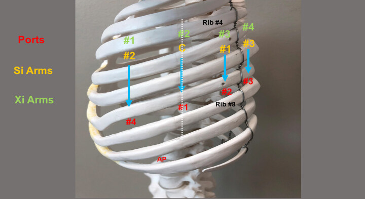
Figure 1. Port placement for robotic lobectomy of the left chest. AP: assistant port
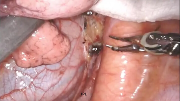
Figure 2. Dissect the inferior pulmonary ligament and remove station #9 and #8 nodes. IPL: inferior pulmonary ligament
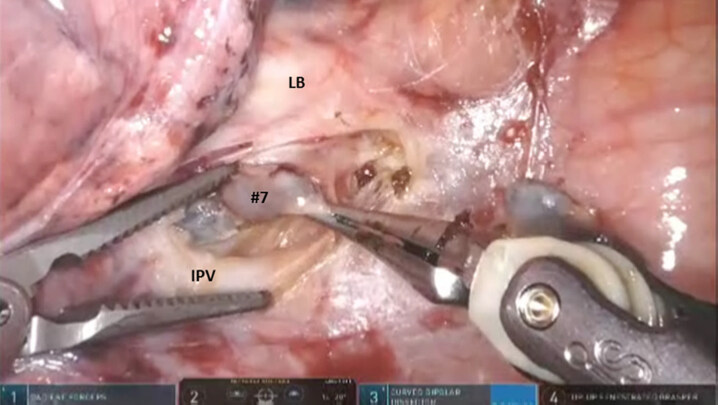
Figure 3. Open the pleura anterior to the vagus nerve. Identify the LB, stay inferior to the edge of the cartilage and remove the nodal bundle of station #7. LB: left bronchus; IPV: inferior pulmonary vein
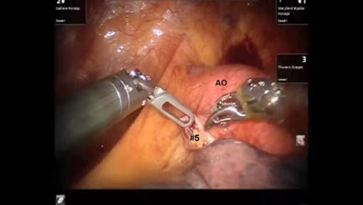
Figure 4. Station #5 nodes are removed. AO: aortic arch
The left main pulmonary artery is identified above the left main bronchus. The space between the pulmonary artery and the bronchus is opened and station #10L nodal bundle is identified overlying the superior border of the bronchus [Figure 5]. The space between the pulmonary artery and the aorta is cleared in order to visualize the nodal bundle that encases the apico-posterior trunk of the artery. Care is taken to identify and preserve the vagus and the recurrent laryngeal branch. After exposing the apico-posterior trunk, the nodal bundle (station #10) is swept in an infero-medial direction, thereby exposing the underside of the truncus branch and its takeoff from the main pulmonary artery [Figures 6 and 7]. The bronchus just deep to the artery is identified. This maneuver facilitates the encirclement of the apico-posterior branch using the Cadiere forceps in the left robotic hand. The pulmonary artery branch is then divided using a stapler with a white vascular cartridge [Figure 8].
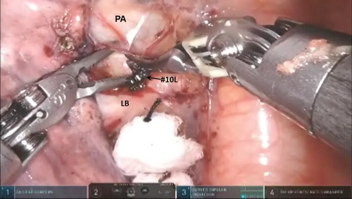
Figure 5. The left main PA is identified above the LB. Station #10L nodes are removed. PA: pulmonary artery; LB: left bronchus
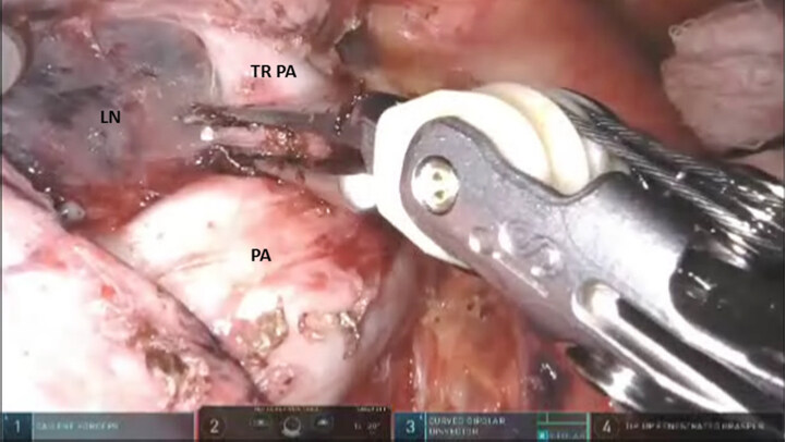
Figure 6. After exposing the apico-posterior trunk (TRPA), the nodal bundle (station #10 LN) is swept in an infero-medial direction. Descending branch of PA. PA: pulmonary artery; TRPA: apico-posterior trunk of left pulmonary artery
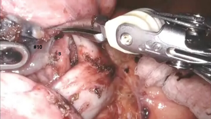
Figure 7. After removing station #10 lymph nodes, the bronchus (B) is identified just deep to the artery
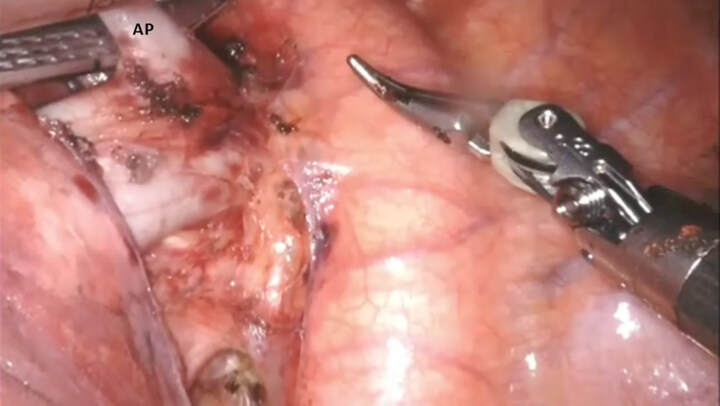
Figure 8. The apical branch of the pulmonary artery (AP) branch is then encircled and divided using a stapler with a white vascular cartridge. AP: apical branch of pulmonary artery
Next, the upper lobe and lower lobe are retracted in opposite directions and the fissure is identified. Dissection of the nodal bundle in station #11 allows for the identification of the pulmonary artery in the fissure. The artery is most superficial at the junction of the lingula, upper lobe and the lower lobe. The sub adventitial plane is entered, and dissection is carried posteriorly under the pulmonary parenchyma in the posterior aspect of the fissure toward the main pulmonary artery [Figure 9]. The Cadiere forceps is used to pass a vessel loop under the pulmonary parenchyma in the posterior aspect of the fissure. A stapler with a blue cartridge is used to divide the tissue in the posterior aspect of the fissure [Figure 10]. The sub-adventitial plane is then developed anteriorly in order to identify the lingular branch of the pulmonary artery. The artery is encircled and divided in a similar fashion with a white cartridge [Figure 11]. Following the division of the lingular artery, the remainder of station #10L node is removed off the underlying bronchus.
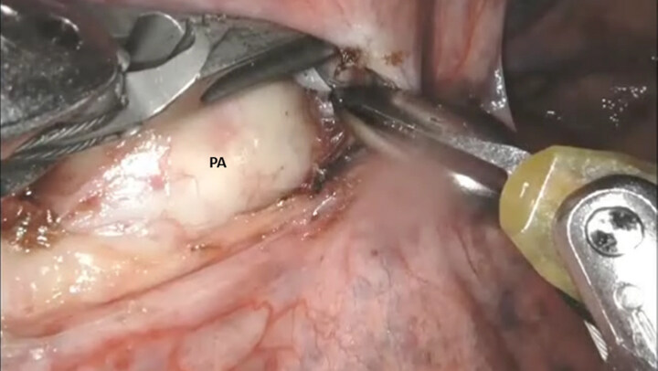
Figure 9. In the main fissure, the sub adventitial plane over the PA is entered, and dissection is carried posteriorly under the pulmonary parenchyma in the posterior aspect of the fissure towards the main PA. PA: pulmonary artery

Figure 10. A vessel loop is passed under the posterior aspect of the fissure, the pulmonary parenchyma is elevated and divided with a stapler carrying a blue load
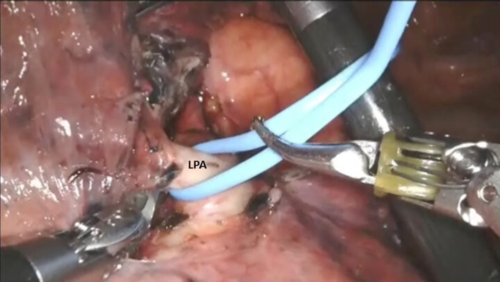
Figure 11. The artery is encircled and elevated with a vessel loop. LPA: lingular pulmonary artery
Next, the lung is retracted posteriorly, the phrenic nerve is identified and the pleura overlying the superior pulmonary vein is incised. From an inferior to superior direction, the superior pulmonary vein is dissected away from the underlying pulmonary artery. Next the superior aspect of the vein is cleared from the pulmonary artery by removing the anterior aspect of the station #10L nodal bundle. The superior pulmonary vein is encircled from an inferior to superior direction using the curved tip thoracic grasper. A vessel loop is passed under the vein and the vein is divided with a stapler using a white vascular cartridge [Figure 12].
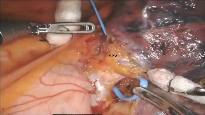
Figure 12. The vessel loop is used to elevate the SPV from the underlying pulmonary artery. SPV: superior pulmonary vein
Division of the superior pulmonary vein allows for the approach to the anterior branch of the upper lobe pulmonary artery. The lung is retracted anteriorly. The Cadiere forceps is to pass under the anterior branch of the pulmonary artery, a vessel loop is used to encircle and elevate the artery branch, and it is divided with a stapler with a white vascular cartridge, which is introduced from a medial to lateral direction [Figure 13].
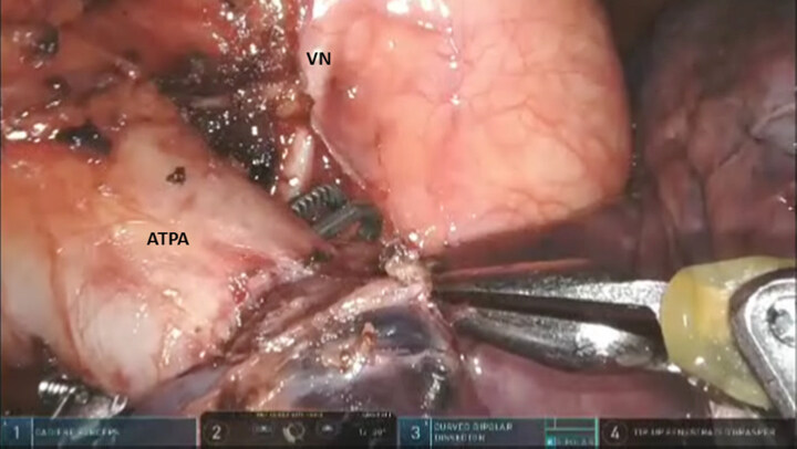
Figure 13. The Cadiere forceps is passed under the ATPA. The VN is seen at the level of the aortic arch. VN: vagus nerve; ATPA: anterior branch of the pulmonary artery
The anterior aspect of the oblique fissure is divided from a medial to lateral direction. This maneuver facilitates the identification of the inferior aspect of the lingular bronchus and thereby, the left upper lobe bronchus. The anesthesiologist is asked to remove the intrabronchial suction catheter. The “Curved Tip-Up” thoracic grasper is passed from an inferior to superior direction under the left upper lobe bronchus, a vessel loop is passed around the bronchus and used to elevate the bronchus, and the bronchus is divided using a stapler with a green cartridge which is passed from an inferior to superior direction [Figure 14].
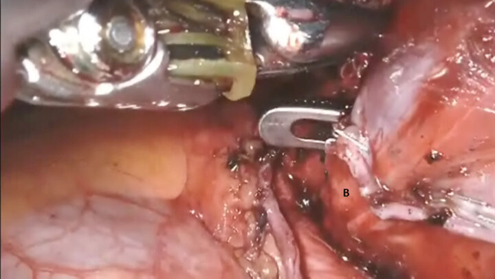
Figure 14. A curved tip forceps is passed from an inferior to superior direction under the left mainstem bronchus (B)
The specimen is placed into the anchor bag and the bag is closed under direct vision ensuring that the entire lobe is inside the bag. The straps are brought out through the access port and used to retrieve the bag containing the lobe.
Left lower lobectomy
Port placement, instruments, and mediastinal nodal dissection are similar to left upper lobectomy.
After mediastinal nodal dissection, the upper lobe and lower lobe are retracted in opposite directions and the fissure is identified. Dissection of the nodal bundle in station #11 allows for identification of the pulmonary artery in the fissure. The artery is most superficial at the junction of the lingula, upper lobe and the lower lobe. The sub adventitial plane is entered, and dissection is carried posteriorly under the pulmonary parenchyma in the posterior aspect of the fissure towards the main pulmonary artery [Figure 15].
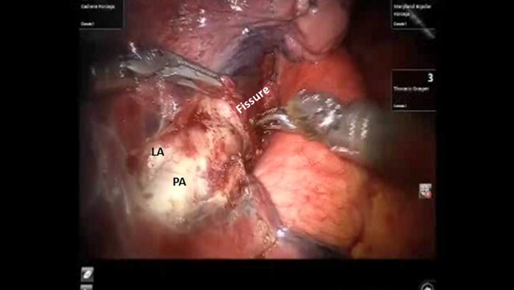
Figure 15. The sub adventitial plane overlying the PA is entered, and dissection is carried posteriorly under the pulmonary parenchyma in the posterior aspect of the fissure towards the main pulmonary artery. LA: lingular artery; PA: pulmonary artery
The Cadiere forceps is used to pass a vessel loop under the pulmonary parenchyma in the posterior aspect of the fissure. A stapler with a blue cartridge is used to divide the tissue in the posterior aspect of the fissure. The sub-adventitial plane is then developed anteriorly in order to identify the lower lobe branch of the pulmonary artery. The anterior aspect of the oblique fissure is divided. The superior segmental pulmonary artery is also identified. The Cadiere forceps is passed under the superior segmental pulmonary artery, a vessel loop is passed underneath and used to encircle and elevate the vessel, and the vessel is divided with a stapler with a white vascular cartridge introduced from a medial to lateral direction [Figure 16]. Next, the lower lobe artery is encircled and divided in a similar fashion with a white cartridge [Figure 17].
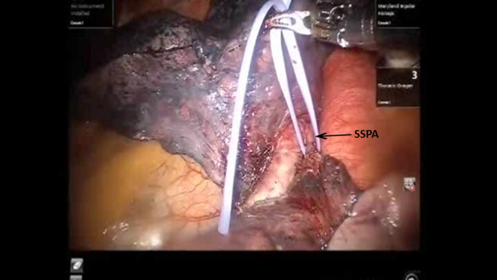
Figure 16. A vessel loop is passed underneath the SSPA and used to encircle and elevate the vessel. SSPA: superior segmental pulmonary artery
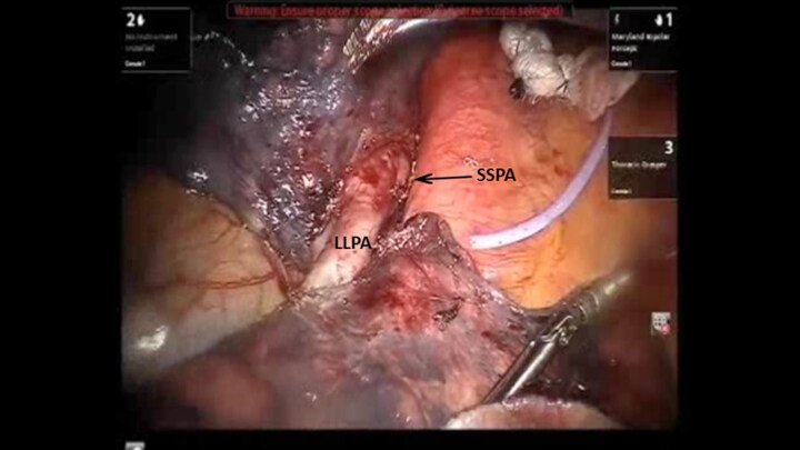
Figure 17. The LLPA is encircled with a vessel loop. Divided end of the SSPA is seen. LLPA: lower lobe pulmonary artery; SSPA: superior segmental pulmonary artery
The lung is elevated and retracted medially. The Cadiere forceps is passed from a medial to lateral direction under the inferior pulmonary vein, a vessel loop is used to encircle and elevate the vein. The inferior pulmonary vein is divided using a stapler with a white vascular load introduced from inferior to superior direction [Figure 18].
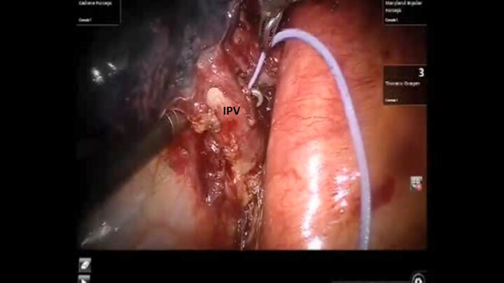
Figure 18. The Cardiere forceps is passed from a medial to lateral direction under the IPV. IPV: inferior pulmonary vein
Finally, the bronchus is divided using a stapler with a purple cartridge [Figure 19]. The lower lobe specimen is removed using the same technique as has been described with the upper lobe.
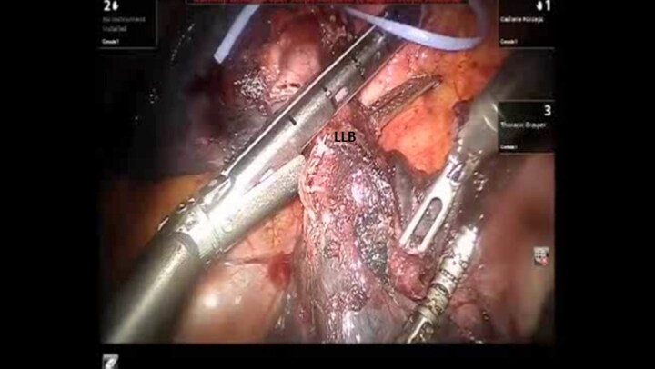
Figure 19. The bronchus to the LLB is divided using a stapler with a purple cartridge. LLB: left lower lobe
Conclusion
Robotic lobectomy has been evolving over the past decade and has been shown to be an oncologically acceptable procedure. A methodical approach to the conduct of the lobectomies and a proven strategy for the control of major vascular injury will increase adoption.
Declarations
Authors’ contributionsCollected the data, performed the procedures, and composed the manuscript: Gharagozloo F, Meyer M
Availability of data and materialsNot applicable.
Financial support and sponsorshipNone.
Conflicts of interestBoth authors declared that there are no conflicts of interest.
Ethical approval and consent to participateNot applicable.
Consent for publicationNot applicable.
Copyright© The Author(s) 2020.
Cite This Article
Export citation file: BibTeX | RIS
OAE Style
Gharagozloo F, Meyer M. The technique of robotic lobectomy II: left sided lobes. Mini-invasive Surg 2020;4:56. http://dx.doi.org/10.20517/2574-1225.2020.43
AMA Style
Gharagozloo F, Meyer M. The technique of robotic lobectomy II: left sided lobes. Mini-invasive Surgery. 2020; 4: 56. http://dx.doi.org/10.20517/2574-1225.2020.43
Chicago/Turabian Style
Gharagozloo, Farid, Mark Meyer. 2020. "The technique of robotic lobectomy II: left sided lobes" Mini-invasive Surgery. 4: 56. http://dx.doi.org/10.20517/2574-1225.2020.43
ACS Style
Gharagozloo, F.; Meyer M. The technique of robotic lobectomy II: left sided lobes. Mini-invasive. Surg. 2020, 4, 56. http://dx.doi.org/10.20517/2574-1225.2020.43
About This Article
Special Issue
Copyright

Data & Comments
Data
0

 Cite This Article 5 clicks

 Like This Article 33
likes
Like This Article 33
likes


Comments
Comments must be written in English. Spam, offensive content, impersonation, and private information will not be permitted. If any comment is reported and identified as inappropriate content by OAE staff, the comment will be removed without notice. If you have any queries or need any help, please contact us at support@oaepublish.com.